Our work
A look at the kind of drawings and documentation we produce. Full project sets — including the ones below — are available on request or via the links at the bottom of this page.
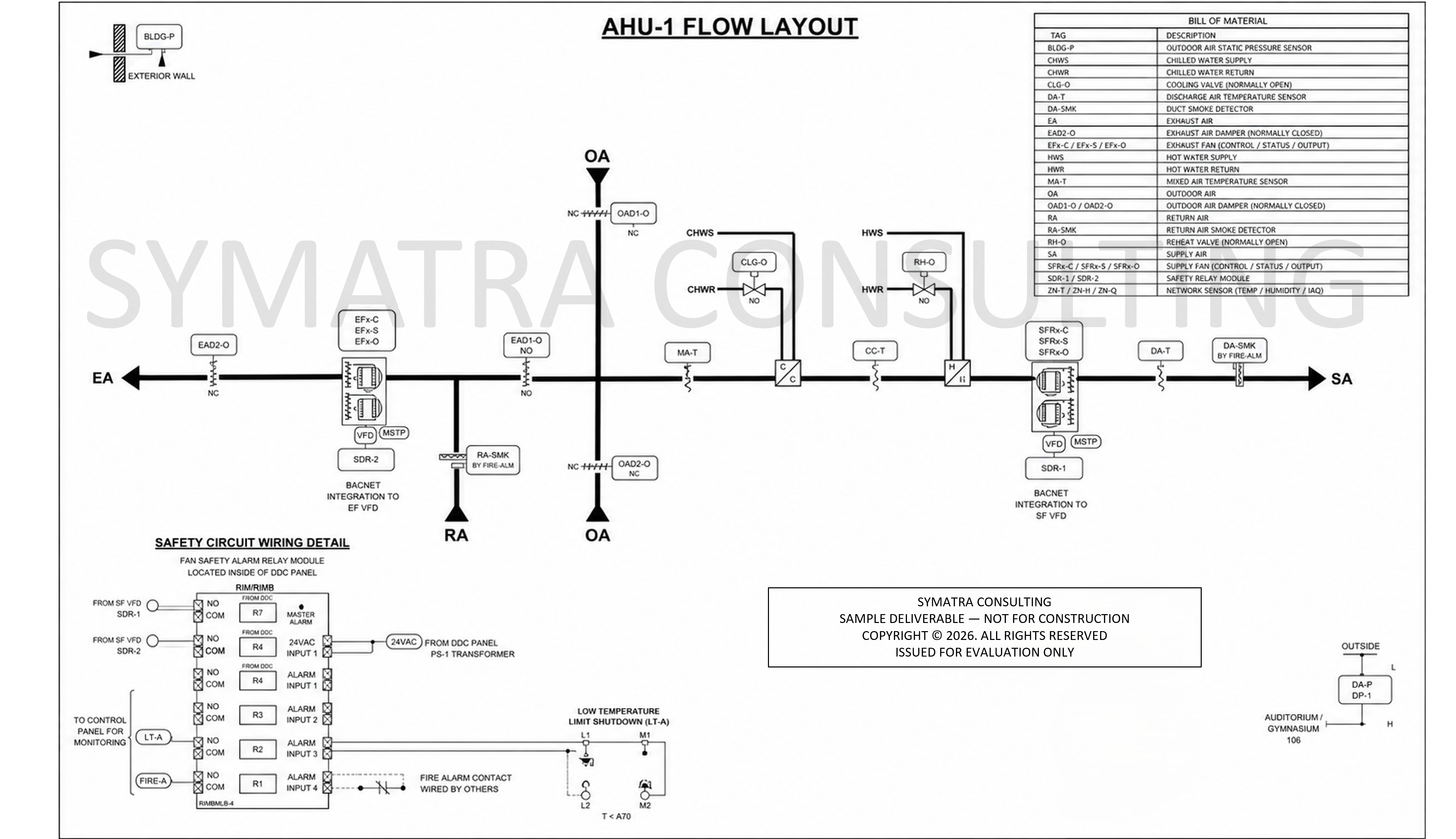
AHU Flow Layout & Safety Relay Detail
Air handling unit schematic with fan safety alarm relay module (RIM/RIMB-4), low-temperature limit interlocks, VFD BACnet integration & complete Bill of Materials.
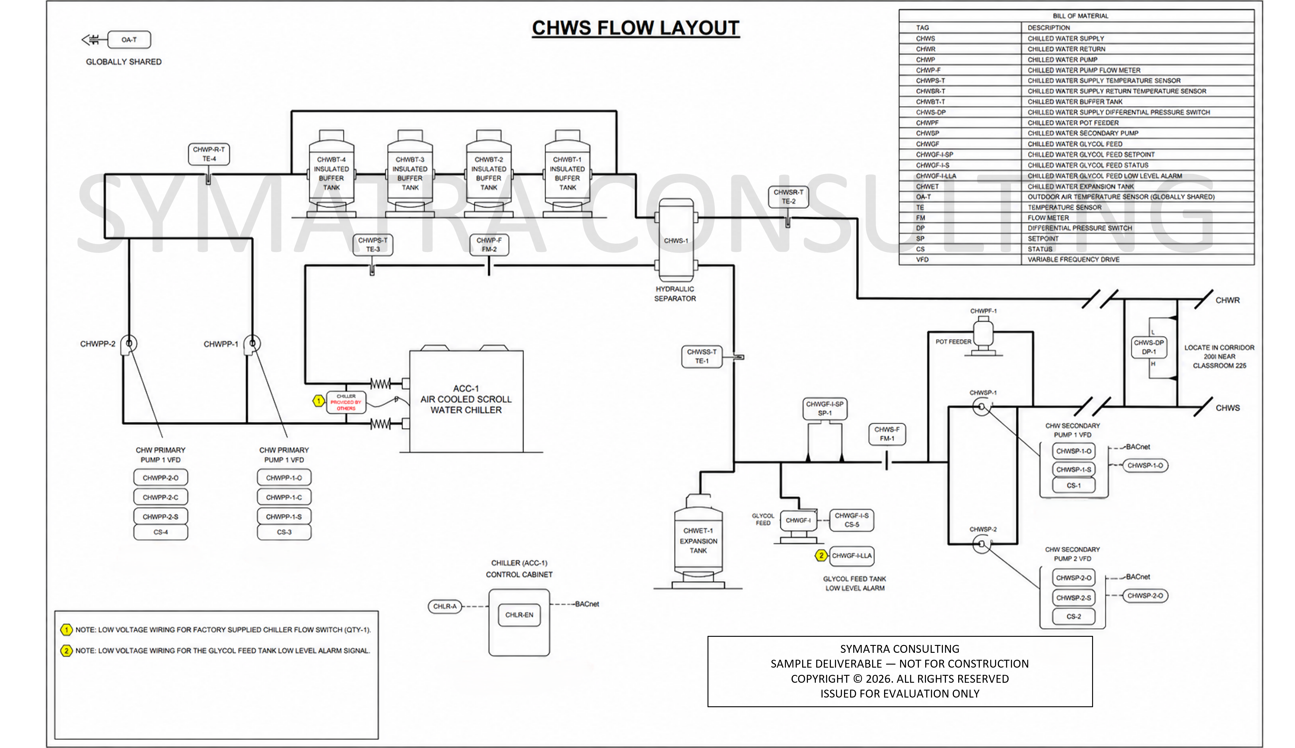
Chilled Water System (CHWS) Flow Layout
Air-cooled scroll chiller (ACC-1), hydraulic separator, 4 insulated buffer tanks, expansion tank & primary/secondary pump decoupling.
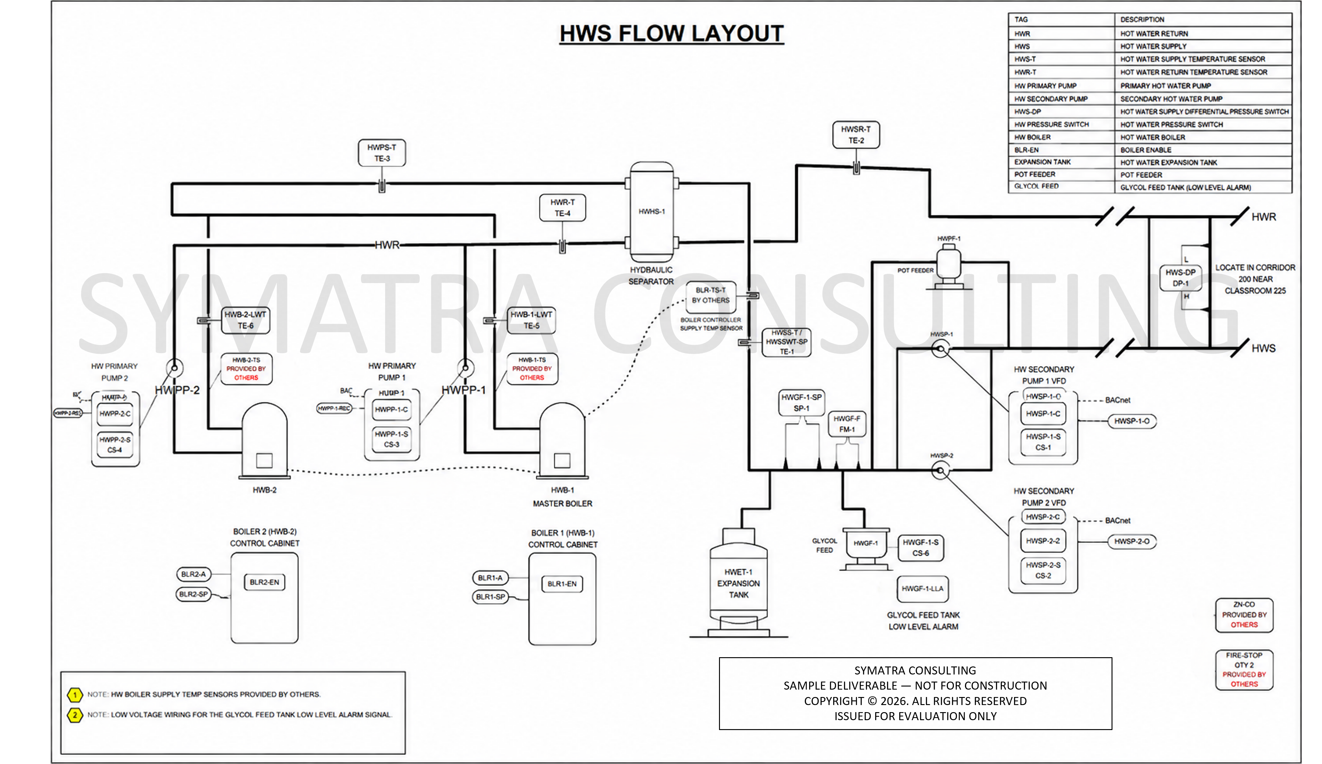
Hot Water System (HWS) Flow Layout
Dual condensing boilers (HWB-1 & 2), hydraulic separator, glycol feed system, expansion tank & secondary VFD distribution.
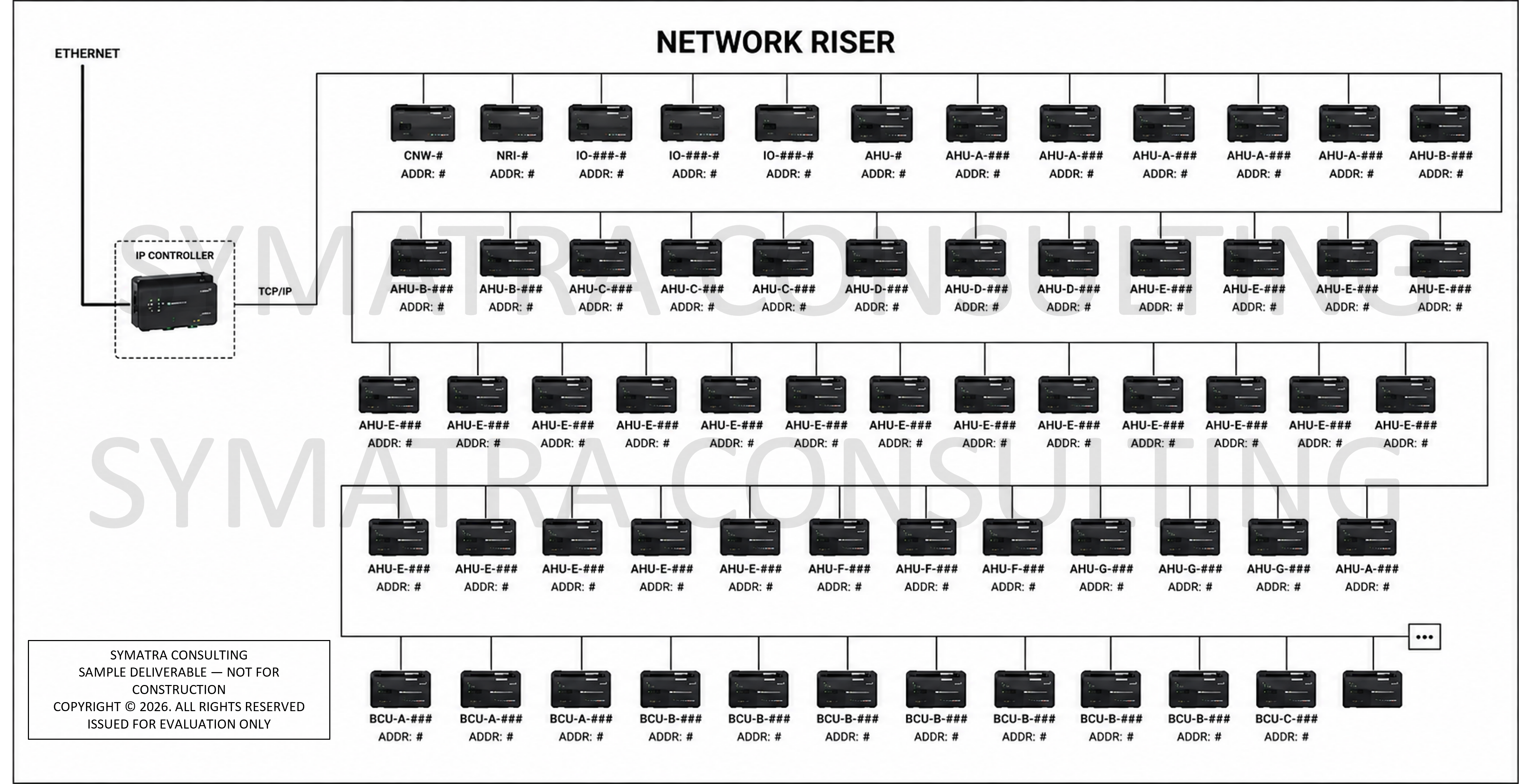
BMS Network Architecture & Riser Diagram
Enterprise IP controller backbone with BACnet MS/TP field controller addressing, segment mapping, and device instance assignments.
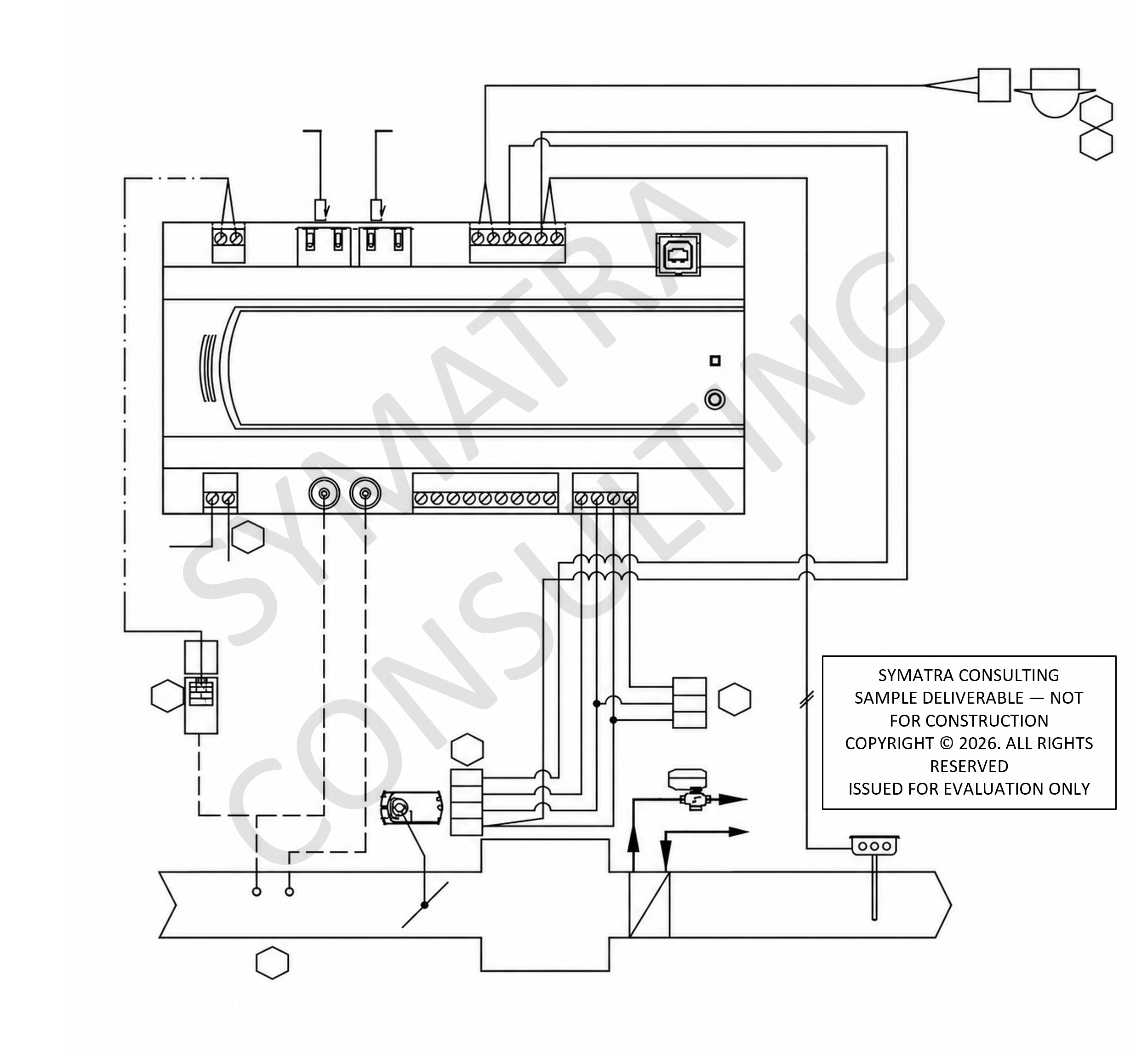
DDC Controller Field Terminations & Point Wiring
Field controller terminal strip mapping for analog inputs (probes, static pressure), digital outputs, damper actuators, and valve control.
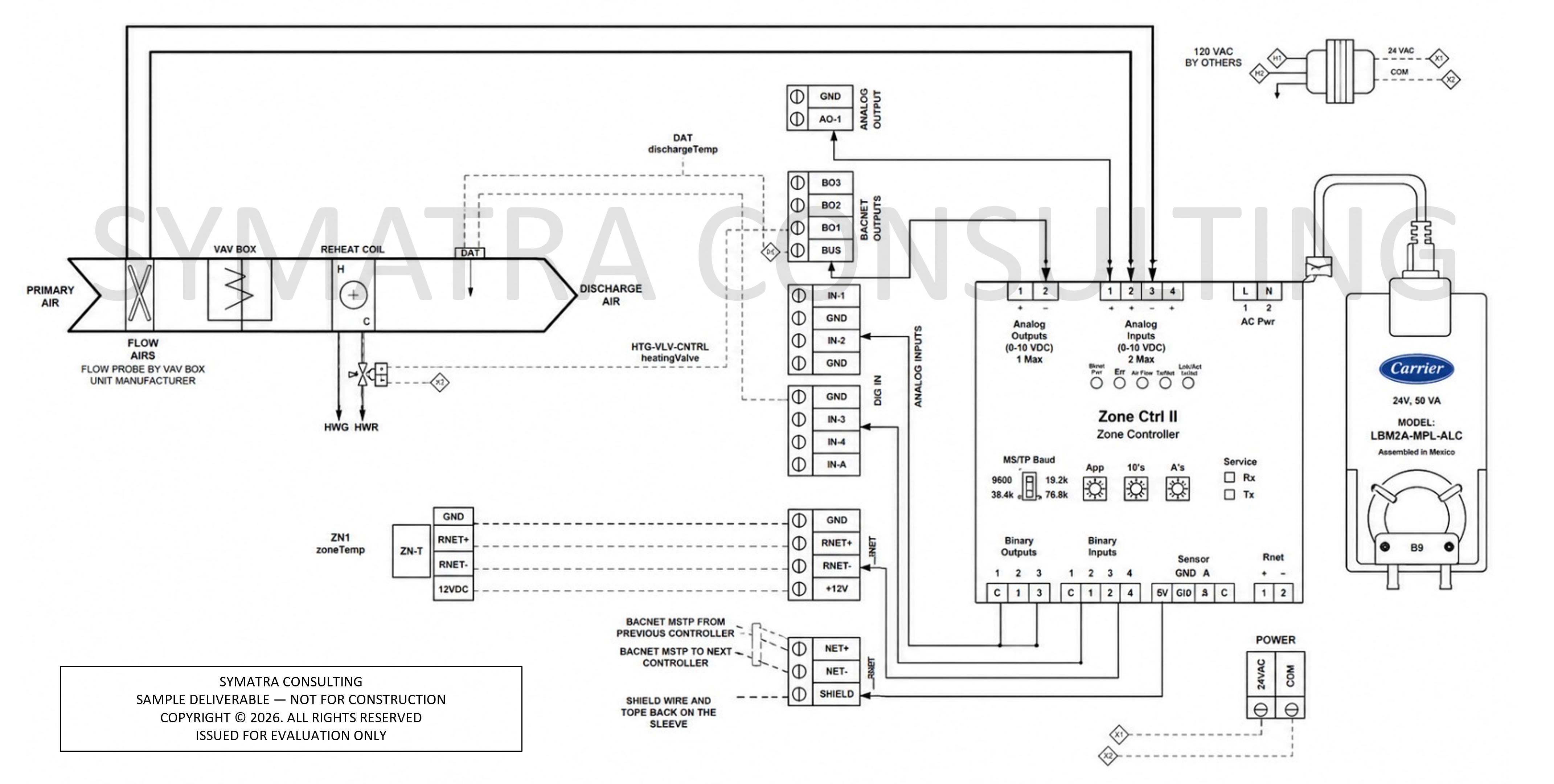
VAV Terminal Box & Controller Wiring Diagram
Pressure-independent VAV box with reheat coil, flow probe, discharge air temperature (DAT), Carrier Zone Ctrl II controller & BACnet MSTP.
Need a tailored submittal package for your project?
We produce custom drawing sets to your exact engineer-of-record specifications, manufacturer cut sheets, and sequence requirements.
Client project submittals are prepared under strict commercial confidentiality and issued privately. The samples above illustrate our drawing standards.